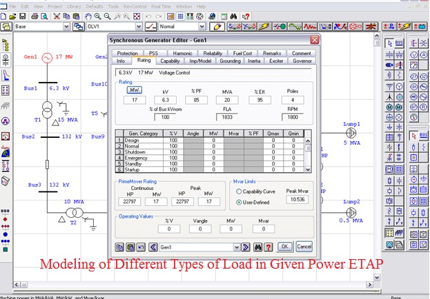
etap generator modeling
19-1 ETAP PowerStation 40 Dynamic Models Induction Machine 191 Induction Machine PowerStation provides five different types of induction machine models which cover all commonly used induction machine designs. ETAP generator modeling - swing voltage control matt111111 Electrical 19 Jun 09 1341 antigfks how expirenced are you with ETAP I just began using it and have a few questions any help would be great.

Etap Load Flow Analysis Generator Overload And Under Excited Problem Electric Motors Generators Engineering Eng Tips
The second order model is the simplest model of synchronous generator which describes only the dynamics of rotor moving 2.
. ETAP includes detailed modeling and simulation of key distribution equipment for steady-state as well as dynamic response. I have modelled one line diagram of a power facility and leave the synchronous. Perform power grid modeling and simulation through this powerful software ETAP Electrical Transient Analyzer Program Image by Author Modeling Simulation software hold great value for Power.
Tell me and I forget. Single1 CKT Model Single2 CKT Model DBL1 CKT Model DBL2 CKT Model. The TIMES model generator combines two different but complementary systematic approaches to modelling energy.
Introduction about Load Flow Analysis with IEEE 3002-2 and IEEE 399. A technical engineering approach and an economic approach. Extend the size of Bus2.
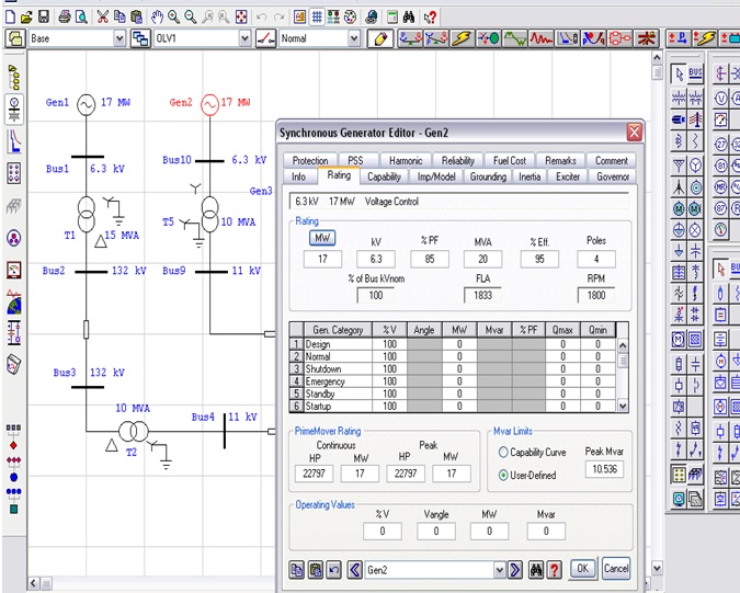
This video takes an insight into power system modelling on ETAP. Generator Model The ETAP generator model complies with the IEEE Standard 1110-2002 2. Transmission Equipment Modeling Key Features High-Voltage DC Transmission Link HVDC Current Source Converter Voltage Source Converter Static Var Compensator SVC Series capacitor.
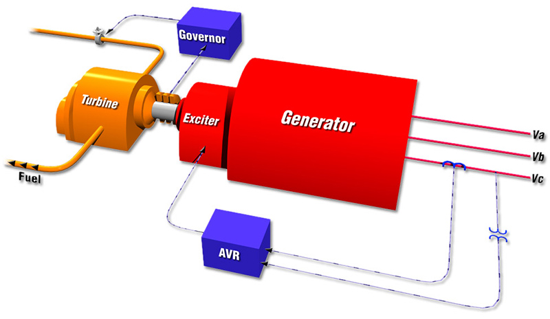
In literature this model is often called the model with constant electro-motive force behind. It is used by various sectors such as Generation Transmission Distribution Industrial Transportation and Low voltage. This model of generator because of it simplicity and good dynamic decryption has the higher usage for analysis and synthesis of control system.
Control modes of generator with simulation capability curve Contingency analysis. Main elements discussed in the video are synchronous generators transformers transmission lines and loads. In these models the stator and rotor reactance and.
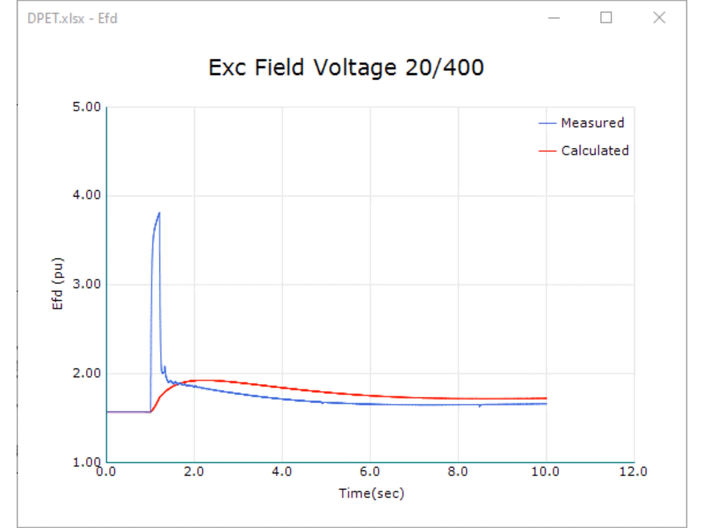
The green line is ETAPs calculation I would expect the curve to look like this if the power source was utility power with no voltage regulation. The generator model used is a sub- transient model and it is represented by two equivalent rotor windings the field winding and a damper winding on the direct axis and two equivalent rotor damper windings on the quadrature axis. ETAP Synchronous generator inertial response.
TIMES is a technology rich bottom-up model generator which uses linear-programming to produce a least-cost energy system optimized according to a number of user constraints over medium to long. Transmission Equipment Modeling ETAP includes detailed modeling and simulation of key transmission equipment for steady-state as well as dynamic system analysis. ETAP has many papers on how to perform this analysis correctly simply use your favorite search engine on the title of your post.
Surge impedance loading simulation with manual calculation Two winding three winding and 3-1 phase winding transformer modelling. Distribution Equipment Modeling Key Features Distribution Segment Junctions Distribution Feeders Lines Cables Substations Switching Stations Jumper Cut Open Point Splice Distribution Transformers Pole Pad Vault. For building and simulating this power network open ETAP and follow the steps.
The red which I drew in using mspaint is what I would expect the actual voltage to look like in my scenario. How can we properly model Synchronous condensor in ETAP. ETAP is an analytical engineering software which is helpful for an electrical engineer to simulate and analyze the steady state and dynamic power system.
Enter four new elements into the one-line diagram and proceed to enter the input data for each element Once all the elements have been connected and the input data has been entered you may proceed to run a Load Flow Calculation. Power factor correction and Reactive Power Compensation. You are trying to model the dynamics of a power system without considering the impact of the turbine-generators governors.

Simulated Power Flow Of Campus Mg Etap Download Scientific Diagram
![]()
Transient Stability Software

Etap Differential Protection Of Motor And Transformer Youtube
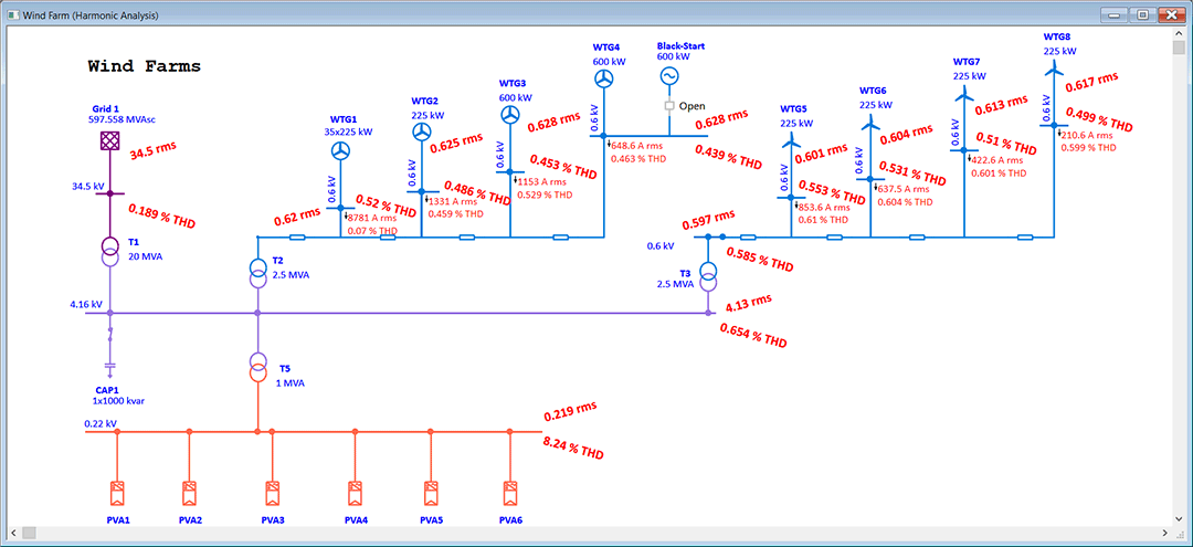
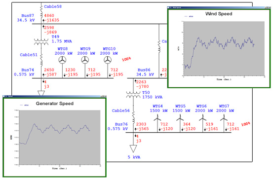
Wind Turbine Generator Wtg Software Wtg Analysis Software Etap
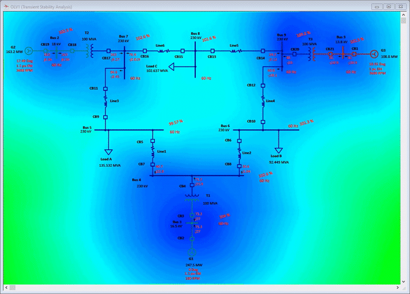
Transient Stability Software Transient Stability Analysis Etap
Generator Start Up Software Generator Start Up Analysis Etap
Load Flow Voltage Drop Analysis Software Powerflow Software Etap

Example Of Grid System Developed In Etap Download Scientific Diagram
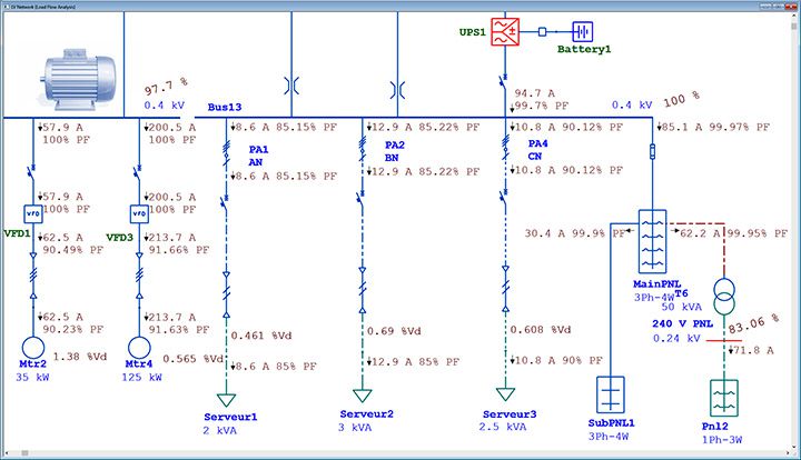
Modeling Of Different Types Of Load In Given Power Etap The Engineering Knowledge
Wind Turbine Generator Wtg Software Wtg Analysis Software Etap
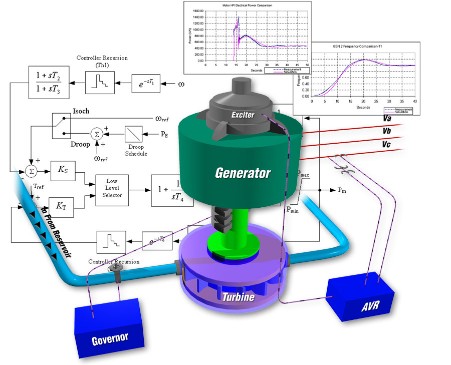
User Defined Dynamic Model Graphical Control Block Diagram Software

Etap Test System For Distributed Power System Download Scientific Diagram

Etap Modeling And Engineering Service Acoylco

Simulated Power Flow Of Campus Mg Etap Download Scientific Diagram

Etap Power System Design And Analysis Course For Solving Various Practical Problems Eep Academy Courses

Detailed Short Circuit Calculation Using Etap Pac Basics

Device Coordination Getting Started With Etap Star Youtube
Dynamic Modeling Tuning
Modeling Of Different Types Of Load In Given Power Etap The Engineering Knowledge


Comments
Post a Comment